
Introduction
In this post, we will discuss a project where two laser beams cross-interfere on a specific surface. A simulation will be performed to verify the image obtained when the lasers hit an IR photodetector. The goal is to determine if the simulation results match the actual data from the IR photodetector.
Basics
Gaussian laser beams are a model for how many real life laser beams behave. While they provide a close approximation, real beams can deviate due to factors like diffraction, lens imperfections, atmospheric effects etc. Gaussian beams are widely used because they closely resemble real world laser behavior.
We will not attempt to explain the theory behind Gaussian laser beams here. Instead, we refer to resources:
- Wikipedia, Gaussian beam (link)
- Lehrstuhl für Lasertechnik LLT, Gaussian beam (link)
- Physics Videos by Eugene Khutoryansky, Diffraction interference patterns with phasor diagrams (link)
Code
It is often more suitable to use a polar coordinate system (instead of Cartesian) when modeling a Gaussian laser beam due to its radial symmetry.
# Polar
#...

for i = 1 : length( z_values )
    z = z_values( i );
    w = w0 * sqrt( 1.0 + ( z / zr )^2 );
    phi = atan( z / zr );

    for j = 1:length( r_values )
        r = r_values( j );
        E( j, i ) = E0 * ( w0 / w ) * exp( -r^2 / w^2 ) * exp( -1i * ( k * z + k * r^2 / ( 2 * z ) - phi ) );
    end
end

#...
# Cartesian
#...

for i = 1:length( z_values )

    z = z_values( i );

    w = w0 * sqrt( 1.0 + (z / zr)^2 );
    phi = atan( z / zr );

    for j = 1:length( x_values )

        x = x_values( j );

        for k = 1:length( y_values )
            y = y_values( k );

            r = sqrt( x^2 + y^2 );

            E( j, k, i ) = E0 * ( w0 / w ) * exp( -r^2 / w^2 ) * exp( -1i * ( k * z + k * r^2 / ( 2.0 * z ) - phi ) );
        end
    end
end

#...
However, if the problem involves angular displacements or transformations (a beam hitting a surface at an angle for example), a Cartesian coordinate system may be more appropriate for handling such transformations.
z1 = -x * sin( alpha ) + z * cos( alpha );
x1 =  x * cos( alpha ) + z * sin( alpha );
y1 =  y;

z2 =  y1 * sin( beta ) + z1 * cos( beta );
x2 =  x1;
y2 =  y1 * cos( beta ) - z1 * sin( beta );
Angle α represents the tilt of the laser beam in the xz-plane (horizontal plane), while angle β represents the tilt in the yz-plane (vertical plane). Together, they describe the beam’s angular deviation from hitting the surface perpendicularly.
Below is an illustration of a electric field when laser beam striking a surface with angles:
$$\alpha = 15°; \beta = 15°$$

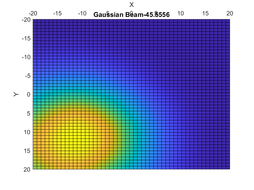
Simulating the cross-interference of laser beams, where one laser hits the surface at a certain angle, creating an elliptical pattern on the surface is yet to come…