Introduction
During development, many problems can arise from incorrect interpretations of datasheets, as well as from taking what is written in them for granted.
In RS422 protocol each signal uses two wires to transmit the data. The differential voltage on the A and B wires represent the digital value. If B>A the value is 1. If A>B then value is 0, or at least it should be…
Our case
The PCB had an MCU with RX and TX lines connected to a MAX3483 transceivers for signal conversion (one for RX and one for TX). After the transceivers, traces continue to pin headers, allowing an FTDI cable to be attached in order to establish communication between the device and PC.
However, when the time came to connect the FTDI cable to the device, some uncertainties arised regarding the correct wiring. Let’s take a look at the datasheets.
MAX3483 communication transceiver

USB to RS422 serial converter cable

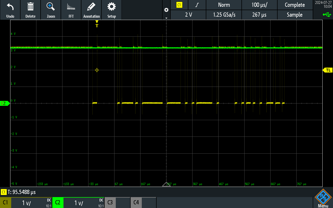
So, how should the RX and TX lines be connected? If the cable is connected incorrectly, the signal can be inverted:

The correct way to connect is:
- A to RXD/TXD +
- B to RXD/TXD -